Pool Equipment Pad Setup: Organizing Your Pump, Filter & Heater for Maximum Efficiency
Your pool equipment pad is the nerve center of your entire pool system. A well-designed equipment pad improves water flow, reduces energy costs, simplifies maintenance, and extends the lifespan of every piece of equipment on it. A poorly laid out pad does the opposite — restricted airflow causes overheating, cramped spacing makes maintenance a nightmare, bad plumbing creates flow restriction, and exposed equipment deteriorates faster in the Texas sun.
Whether you're building a new pool, upgrading old equipment, or reorganizing your current pad, here's everything you need to know about getting the layout right.
Equipment Pad Basics
What Goes on an Equipment Pad
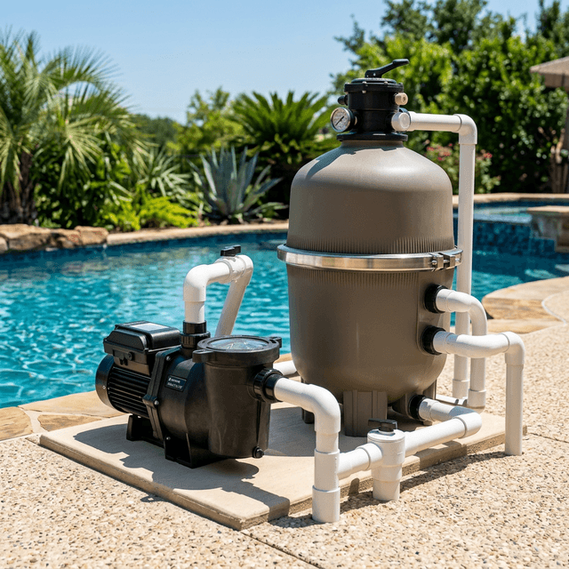
A typical residential pool equipment pad includes:
- Pool pump (single-speed, dual-speed, or variable speed)
- Filter (cartridge, DE, or sand)
- Heater (gas or heat pump) — if equipped
- Salt chlorine generator cell and control box — if saltwater pool
- Pool automation controller — if equipped
- Chemical feeder (chlorinator or acid feeder) — if equipped
- Booster pump (for pressure-side pool cleaners) — if equipped
- Valve actuators (for pool/spa combos or water features)
- Electrical subpanel or disconnect
- Plumbing manifold (suction and return lines, valves)
The Pad Itself
The equipment pad should be a flat, level concrete slab, typically 4 inches thick, with proper drainage. It needs to be:
- Level — pumps, filters, and heaters all require level installation for proper operation
- Sized correctly — large enough for current equipment plus room for future additions
- Properly drained — water from backwash, filter cleaning, and rain should drain away from equipment and away from the house foundation
- Accessible — technicians need room to work around every piece of equipment
- Close to the pool — but not so close that noise is an issue (more on this below)
Typical pad size: Most residential pools need an equipment pad that is at least 4 feet by 8 feet. Pools with heaters, automation, salt systems, and booster pumps may need 5 feet by 10 feet or larger.
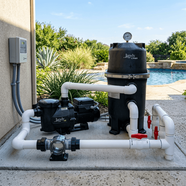
Ideal Equipment Layout
The order of equipment matters. Pool water flows through your equipment in a specific sequence, and the layout should follow this flow to minimize plumbing bends, reduce friction loss, and optimize efficiency.
Standard Flow Sequence
Here's the order water travels through your equipment:
- Skimmer and main drain (in-pool) to suction plumbing
- Pump — pulls water from the pool
- Filter — removes debris and particles
- Heater — heats the water (if equipped)
- Salt cell — generates chlorine (if equipped)
- Chemical feeder — adds chlorine or acid (if equipped)
- Return plumbing — back to the pool
The layout on your pad should mirror this sequence from left to right or front to back. This minimizes the plumbing distance between each component, reduces elbows and turns, and allows gravity and flow to work efficiently.
Recommended Layout Diagram
Here's a practical layout that works for most residential pools:
[Pool suction lines]
        |
    [PUMP] -----> [FILTER] -----> [HEATER] -----> [SALT CELL]
        |                                               |
[Booster pump]                                    [Return to pool]
(if applicable)

[Automation controller]     [Electrical subpanel]
(mounted on wall or post)   (mounted on wall or post)
Layout Rules
- Pump goes first in the equipment sequence and should be closest to the pool's suction lines
- Filter goes directly after the pump — the shorter the plumbing run between pump and filter, the better
- Heater goes after the filter — always. Sending unfiltered water through a heater will clog the heat exchanger and void the warranty
- Salt cell goes after the heater — the chlorine generated by the cell is corrosive to heater components, so it must be downstream
- Chemical feeders go last — same principle as the salt cell, after all other equipment
- Automation controllers mount vertically on a wall, post, or equipment stand — not on the ground
Spacing Requirements
Crowding equipment together is one of the most common mistakes homeowners and even some builders make. Every piece of equipment needs clearance for three reasons: airflow, maintenance access, and code compliance.
Minimum Spacing Guidelines
| Equipment | Minimum Clearance |
|---|---|
| Pump | 12 inches on all sides for ventilation and access |
| Filter | 24 inches above for lid removal; 12 inches on sides for access |
| Gas heater | 12 inches on sides, 36 inches above (check manufacturer specs — some require more) |
| Heat pump | 24-36 inches on all sides for airflow — heat pumps need significant air circulation |
| Salt cell | Accessible for removal and inspection — plan for 18+ inches of straight pipe on either side |
| Automation panel | 18 inches in front for door opening; at eye height for visibility |
| Electrical subpanel | 36 inches clear in front (NEC code requirement) |
Why Spacing Matters
- Gas heaters produce exhaust. Restricted clearance above or around a gas heater creates a fire hazard and causes premature corrosion from trapped exhaust gases.
- Heat pumps move massive volumes of air across a coil. Restricted airflow means the heat pump works harder, runs longer, and costs more to operate. Never place a heat pump against a wall or fence on more than one side.
- Filters need space above to remove the lid for cartridge changes or DE grid servicing. If you can't fully remove the filter lid without hitting an obstacle, the filter is too close to something.
- Pumps generate heat and need ventilation. Variable speed pumps run cooler than single-speed, but all pumps benefit from airflow.
Plumbing Best Practices
Bad plumbing is one of the biggest efficiency killers in pool systems. Every unnecessary elbow, every undersized pipe, and every overly long run reduces flow and forces the pump to work harder.
Pipe Sizing
- Suction side (before the pump): Use 2-inch pipe minimum. Larger is better — 2.5 inch or 3 inch reduces friction loss significantly and is especially important for variable speed pumps running at low RPMs.
- Pressure side (after the pump): 2-inch pipe is standard. Can reduce to 1.5 inch for individual return lines at the pool.
- Never reduce pipe size on the suction side. Undersized suction piping restricts flow and causes pump cavitation (air bubbles), which damages the pump and reduces efficiency.
Reducing Friction Loss
Friction loss is the resistance water encounters as it flows through pipes, fittings, and equipment. Less friction loss means your pump moves more water with less energy.
- Minimize elbows. Every 90-degree elbow adds friction equivalent to approximately 5-7 feet of straight pipe. Use 45-degree elbows or sweep 90s (long-radius bends) when possible.
- Keep runs short. The equipment pad should be as close to the pool as practical — long pipe runs waste energy.
- Use sweep fittings, not sharp elbows. Sweep 90-degree fittings have a larger radius and create significantly less friction than standard 90-degree elbows.
- Avoid unnecessary valves on the suction side. Every valve adds restriction. Only install valves where they are functionally necessary.
- Use unions at equipment connections. Unions allow you to disconnect equipment for service without cutting pipe. Install a union on both sides of the pump, filter, heater, and salt cell.
Plumbing Layout Tips
- Run suction and return lines parallel from the pool to the equipment pad — this keeps plumbing organized and makes future troubleshooting easier.
- Slope suction piping slightly downward toward the pump to help with priming and prevent air locks.
- Install check valves where needed — especially on elevated spas or water features to prevent backflow and water draining out of the system.
- Label all pipes. Mark suction, return, spa suction, spa return, water feature, and cleaner lines. Your future self (and any technician) will thank you.
Electrical Requirements and Safety
Pool equipment electrical work is governed by the National Electrical Code (NEC) Article 680, which covers swimming pools, spas, and hot tubs. This is not DIY territory — pool electrical must be done by a licensed electrician.
Key Electrical Requirements
- Dedicated circuit for the pump. Most variable speed pumps require a dedicated 20-amp, 240-volt circuit. Check the pump manufacturer's specifications.
- Dedicated circuit for the heater. Gas heaters typically need a 120V circuit for ignition and controls. Heat pumps need a dedicated 30-60 amp, 240V circuit depending on size.
- GFCI protection. All pool equipment circuits must have ground fault circuit interrupter protection — this is code and it saves lives.
- Bonding. All metal pool equipment, the pool shell, rebar, metal plumbing, and handrails must be bonded together with a continuous copper bonding wire. This equalizes voltage potential and prevents electric shock.
- Equipment grounding. Every piece of electrical equipment must be grounded individually back to the electrical panel.
- Disconnect switch. A visible, lockable disconnect must be installed within sight of the pool equipment, at least 5 feet from the pool edge.
- Minimum distances. Electrical outlets, switches, and panels must be at least 5 feet from the pool's edge (10 feet for some overhead wiring). Check NEC 680 for specific requirements.
Automation Wiring
If you're installing pool automation (see our Pool Automation Systems Guide), plan for:
- Low-voltage wiring between the automation controller and actuators, temperature sensors, and salt cell
- Communication wiring between the controller and any remote displays or wireless modules
- Conduit for future expansion — it's much easier to run an extra conduit during construction than to trench later
- Wi-Fi access — most modern automation systems need a wireless connection. Ensure your pad location is within range of your home's Wi-Fi or plan for a network extender
Noise Reduction
Pool equipment generates noise, and in DFW neighborhoods where houses are close together, noise complaints are real. Planning for noise during the equipment pad design phase is much easier than trying to fix it after installation.
What Creates Noise
| Equipment | Noise Level | Notes |
|---|---|---|
| Single-speed pump | 65-80 dB | Loud — equivalent to a vacuum cleaner running continuously |
| Variable speed pump (low speed) | 40-55 dB | Quiet — comparable to a refrigerator |
| Variable speed pump (high speed) | 60-70 dB | Still quieter than single-speed |
| Gas heater | 50-65 dB | Moderate; exhaust fan contributes most of the noise |
| Heat pump | 55-70 dB | Fan noise is the primary source; compressor adds vibration |
| Filter | Minimal | Filters are essentially silent |
| Booster pump | 65-75 dB | Runs for shorter periods but quite loud |
Noise Reduction Strategies
-
Use a variable speed pump. Running at 1,100-1,800 RPM instead of 3,450 RPM drops noise levels dramatically. This is the single most effective noise reduction upgrade you can make. See our full guide on variable speed pumps.
-
Place the equipment pad away from bedrooms and patios. If possible, position the pad on the side of the house that faces away from living areas and neighboring homes.
-
Use vibration isolation pads under the pump and booster pump. Rubber or neoprene pads absorb vibration and prevent noise from transmitting through the concrete pad.
-
Build a sound barrier wall. A solid masonry or composite wall on the side facing living areas blocks significant noise. Ensure the wall does not restrict airflow to heat pumps or gas heater exhaust.
-
Avoid enclosing equipment completely. A roofed and walled enclosure traps heat, restricts airflow, and can create dangerous conditions for gas heaters. If you build an enclosure, leave the top open and ensure adequate ventilation on all sides.
-
Schedule high-speed run times wisely. If your pump needs to run at high speed for vacuuming or spa jets, schedule it during daytime hours when ambient noise is higher.
DFW-Specific Equipment Pad Concerns
Freeze Protection
North Texas gets freezing temperatures several times per winter, and ice storms can knock out power for hours or days. Your equipment pad setup must account for freeze events.
Freeze protection measures:
- Freeze guard sensor — install a temperature sensor on the equipment pad that triggers the pump and heater to run when temps approach 35-38 degrees F. Most pool automation systems include this feature. See our automation guide for details.
- Insulate exposed pipes — any above-ground plumbing on the equipment pad should be insulated with pipe insulation or heat tape. Focus on the pump volute, filter connections, and any elevated plumbing.
- Pipe routing — keep pipes below ground as much as possible. Exposed above-ground pipe runs are vulnerable to freezing.
- Drainage valves — install drain plugs or petcocks at low points in the plumbing so you can drain equipment if you lose power during a freeze.
- Backup power consideration — a small portable generator that can run the pump during extended power outages is worth the investment in North Texas. The pump only needs to circulate water to prevent freezing — it does not need to run at full speed.
For a complete freeze preparedness guide, see What to Do After a Pool Freeze.
Sun and Heat Exposure
Texas sun degrades equipment. UV radiation breaks down plastic components, fades labels, and can cause PVC pipe and fittings to become brittle over time.
Protection strategies:
- Shade structure — a pergola, shade sail, or simple roof over the equipment pad reduces UV exposure significantly. Ensure it does not restrict airflow, especially for heat pumps and gas heater exhaust.
- UV-resistant pipe — if any PVC pipe is exposed to direct sunlight, paint it with UV-resistant paint or wrap it with UV-protective tape. Unpainted PVC degrades noticeably within 2-3 years in direct Texas sun.
- Equipment orientation — position the automation controller display and any digital readouts away from direct afternoon sun (west-facing). Sun and heat on LCD displays shortens their lifespan.
DFW Soil Conditions
Much of the DFW area, particularly Northlake, Argyle, Flower Mound, and Haslet, has expansive clay soil. This soil expands when wet and contracts when dry, which can cause concrete pads to shift, crack, or heave over time.
Mitigation:
- Proper pad preparation — the soil beneath the equipment pad should be compacted and, ideally, a layer of crushed gravel or sand should be placed under the concrete for drainage and stability.
- Reinforcement — use rebar or wire mesh in the concrete pad to resist cracking from soil movement.
- Drainage — ensure water drains away from the pad. Standing water under or around the pad accelerates soil movement.
- Flexible plumbing connections — use flexible PVC or rubber couplings where plumbing transitions from underground to above-ground. This allows some movement without cracking rigid PVC joints.
Common Equipment Pad Mistakes
1. Pad Too Small
The number one mistake. Builders sometimes pour a pad that fits the initial equipment with zero room to spare. Then you add a salt system, or a booster pump, or upgrade to a larger filter, and there's no room. Always oversize your pad by at least 20%. The extra concrete costs very little during construction and saves a fortune if you ever need to expand.
2. Poor Drainage
Equipment pads that sit in standing water after rain or backwash create corrosion, mosquito breeding, and soil erosion problems. The pad should be slightly elevated or sloped to drain away from equipment and the house foundation.
3. Equipment Crammed Against a Fence or Wall
This restricts airflow, makes maintenance impossible (technicians can't access the back of equipment), and violates clearance requirements for gas heaters and heat pumps. Leave at least 18-24 inches between equipment and any wall or fence.
4. No Unions or Service Access
If equipment is plumbed in with glued connections and no unions, removing a pump for repair means cutting pipe. Unions at every equipment connection make service faster and cheaper. This is a small upfront cost that saves significant labor costs over the life of the equipment.
5. Ignoring Noise
Equipment placed directly against a bedroom wall or patio will generate complaints — from your family and potentially your neighbors. Plan the pad location with noise in mind from the start.
6. Exposed Wiring and Plumbing
All wiring should be in conduit. All plumbing transitions should be clean and supported. Sloppy wiring and plumbing isn't just ugly — it's a safety hazard, a code violation, and it deteriorates faster.
7. No Room for a Technician
If a service technician can't comfortably access every valve, union, and connection point, maintenance takes longer and costs more. Tight spaces also increase the chance of accidental damage during service.
Upgrading an Old Equipment Pad
If your existing pad is undersized, cracked, or poorly laid out, here's how to approach an upgrade:
Assessment
- Measure the existing pad and identify what's too small or poorly positioned
- List all current equipment plus anything you plan to add (salt system, automation, heater upgrade)
- Note any drainage issues, cracking, or soil movement
- Check electrical capacity — older pools may have undersized wiring for modern equipment
Upgrade Options
Option 1: Expand the existing pad. Pour additional concrete adjacent to the existing pad. This works if the current pad is in good condition and just needs more space.
Option 2: Replace the pad entirely. If the pad is cracked, heaved, or poorly located, it may be more cost-effective to pour a new pad in a better location and re-route plumbing and electrical.
Option 3: Equipment-only upgrade on the existing pad. If the pad size is adequate but the layout is poor, replacing equipment one piece at a time with better plumbing and layout can improve things significantly without the cost of a new pad.
Cost Expectations
- New concrete pad (4x8): $500-$1,200 depending on site preparation
- Plumbing rework: $300-$800 for replumbing equipment connections
- Electrical update: $500-$2,000 depending on scope (new circuits, subpanel, GFCI, bonding)
- Complete equipment pad overhaul (pad + plumbing + electrical): $1,500-$4,000+
Energy Efficiency Starts at the Pad
A well-designed equipment pad directly impacts your energy costs. Proper pipe sizing, minimal friction loss, efficient equipment layout, and smart automation all reduce how hard your pump has to work — which reduces electricity consumption.
For more on maximizing energy efficiency, see our guides on:
- Are Variable Speed Pumps Worth It? — the single biggest energy upgrade
- Pool Automation Systems Guide — automate scheduling for peak efficiency
- 10 Ways to Reduce Pool Energy Costs — comprehensive energy savings strategies
We Design, Install, and Upgrade Equipment Pads
Visit our Northlake pool supply store for pumps, filters, heaters, salt systems, automation controllers, and all the components you need for your equipment pad. Browse our full catalog at our online shop.
Need professional installation or an equipment pad upgrade? Our team designs and installs equipment pads throughout the DFW North area — Northlake, Argyle, Flower Mound, Trophy Club, Denton, Highland Village, Lewisville, Southlake, Corinth, Lantana, Cross Roads, and Haslet. We'll make sure your pad is sized right, laid out for efficiency, and built to handle Texas weather.
Call us at (469) 455-1054 or contact us online to schedule a consultation. A properly set up equipment pad saves you money and headaches for years to come.